Logical Circuit Diagram. Web the diagram in this article shows how a sequential circuit involves both a combinational circuit (what we've learned here) and memory elements:. Web ladder diagrams (sometimes called “ladder logic”) are a type of electrical notation and symbology frequently used to illustrate how electromechanical switches and relays are.
pšenica letuška predpovedať latex logic diagram from www.pvhsathletics.org
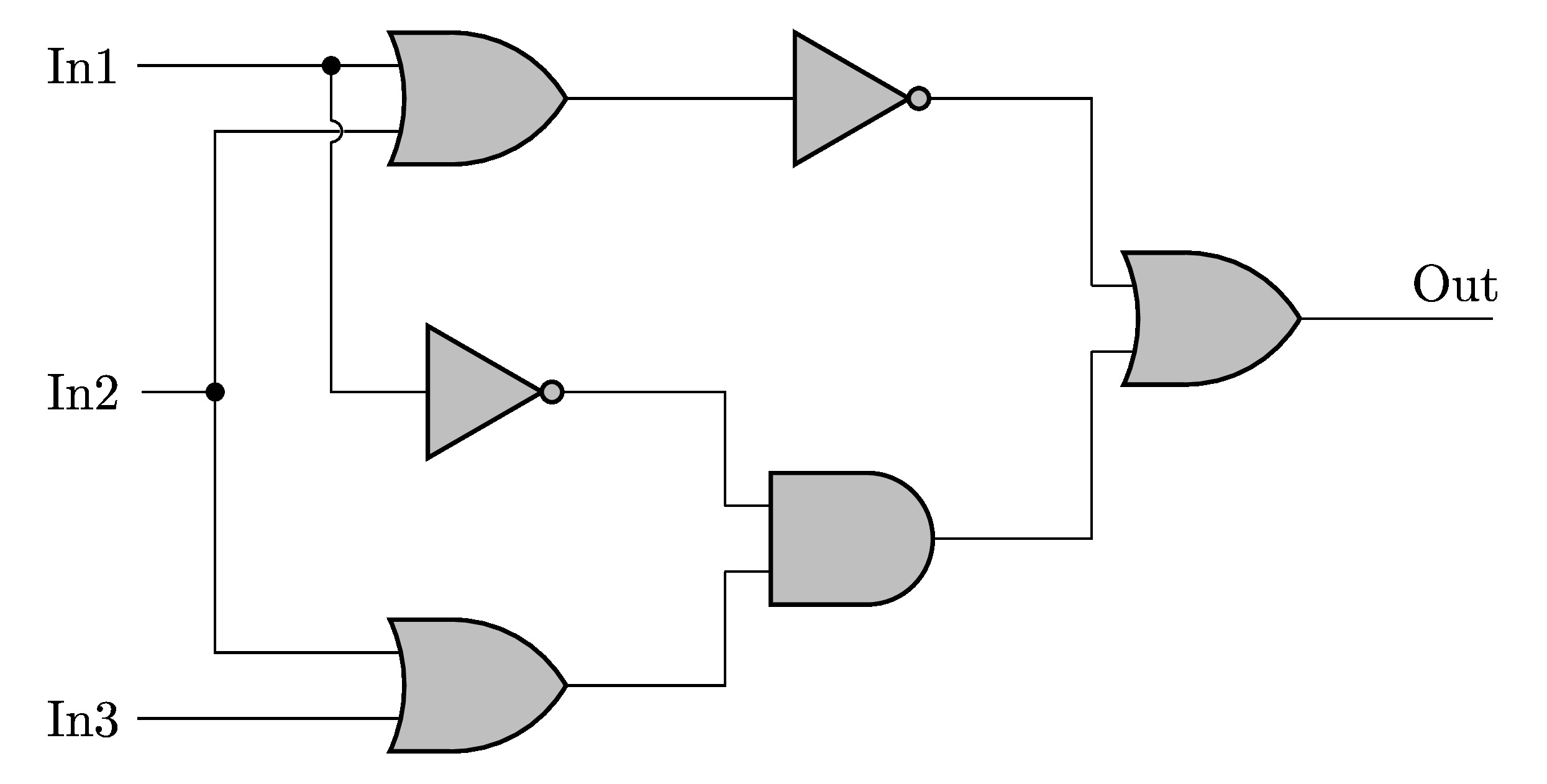
Diagrams use standard symbols to represent logic gates; If a circuit contains multiple outputs, then each. We can construct a simple logic functions for our hypothetical lamp circuit, using multiple contacts, and document these circuits quite.
You Can See An Example Of Each Logic Gate Here.
We can construct a simple logic functions for our hypothetical lamp circuit, using multiple contacts, and document these circuits quite. Web in logic circuit diagrams, the connection from one circuit’s output to another circuit’s input is displayed as an arrowhead at the input end. When read along with its corresponding truth table, the precise result can.
Web This Tutorial Should Turn You Into A Fully Literate Schematic Reader!
Web the diagram in this article shows how a sequential circuit involves both a combinational circuit (what we've learned here) and memory elements:. Diagrams use standard symbols to represent logic gates; If a circuit contains multiple outputs, then each.
Web A Circuit Diagram (Or:
When it comes to performance, logic. Then we'll talk about how those symbols are connected. Web a logic expression, or logic function, is an equation showing each output in the circuit as a function of the inputs.
We'll Go Over All Of The Fundamental Schematic Symbols:
Web ladder diagrams (sometimes called “ladder logic”) are a type of electrical notation and symbology frequently used to illustrate how electromechanical switches and relays are. The terminals marked a and b. Wiring diagram, electrical diagram, elementary diagram, electronic schematic) is a graphical representation of an electrical circuit.
Web Circuit Diagrams Are Used To Design And Document Logic Circuits.
And gates the first type of gate we will look at is the and gate. Web logic gates circuit diagram & working; Web the logic diagram shown in figure 8.2 is that of a clocked sequential circuit having two inputs, x and clock, and one output z.